Home
› Ls1 Maf Wiring Diagram / Maf Wiring Schematic Camaro5 Chevy Camaro Forum Camaro Zl1 Ss And V6 Forums Camaro5 Com / This wire is yellow and leads to pin 31 on the ls1 c2 ecu connector.
Ls1 Maf Wiring Diagram / Maf Wiring Schematic Camaro5 Chevy Camaro Forum Camaro Zl1 Ss And V6 Forums Camaro5 Com / This wire is yellow and leads to pin 31 on the ls1 c2 ecu connector.
Ls1 Maf Wiring Diagram / Maf Wiring Schematic Camaro5 Chevy Camaro Forum Camaro Zl1 Ss And V6 Forums Camaro5 Com / This wire is yellow and leads to pin 31 on the ls1 c2 ecu connector.. I'm reading these maf threads and everyone keeps mentioning the g8 maf wiring. All psi harnesses are made in the usa. It sounds like this is an issue with the wires leading to the maf. Each part ought to be placed and connected with different parts in particular way. Between the maf (mass air flow sensor) and engine's throttle body.
If the wires are good, next thing i would do is get a known working maf and swap it in. Ls engine swap wiring diagram basic engine wiring diagram chevy chevy ls1 swap wiring diagram swap wiring harness ls1 coil wiring. Pink wire is from the engine sensors fuse in the underhood fuse block. I'm reading these maf threads and everyone keeps mentioning the g8 maf wiring. The easiest is to buy the adapter wiring harness and ls1 calibrated maf from pace parts.
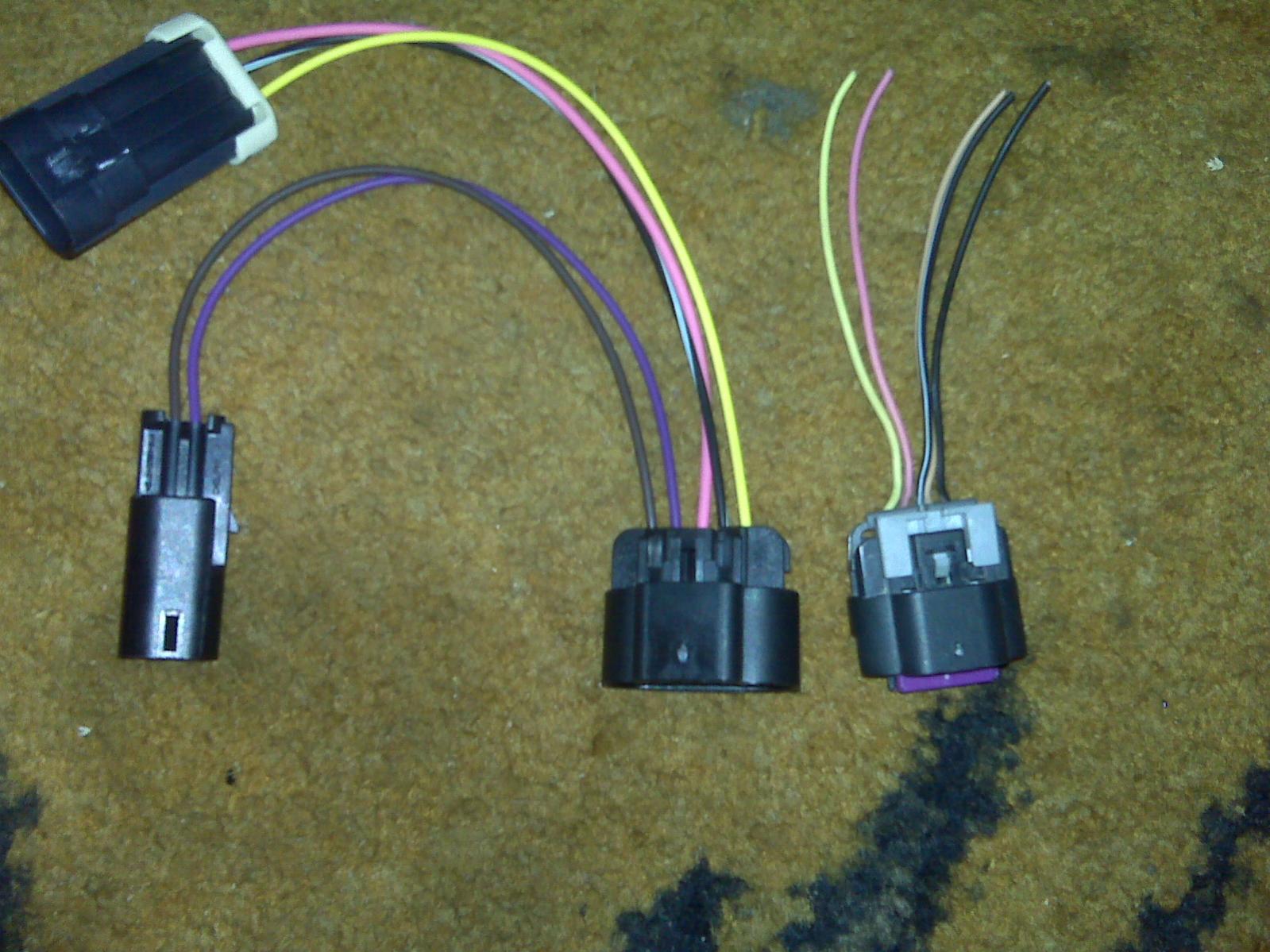
5 Wire Gm Mass Air Flow Sensor Connector Pigtail Maf Corvette Ls1 Ls2 Ls6 Ebay from i.frg.im These directions will likely be easy to grasp and apply. 98 camaro engine wiring diagram ls1 var 1998 pdf for tracker starter circuit wireing harness 2004 gm ls6 efi pcm ignition 1 feed ls1tech g ecu pinout 1999 2002 my pro street 93 lt1 to conversion o2 jaguar specialties corvette fuel line firebird procharger need boss rt3 chevy and pontiac 1993 alternator 97 r. All psi harnesses are made in the usa. Pin c or the middle pin is the mass air flow. Each part ought to be placed and connected with different parts in particular way. The individual harness part number that come in the kit is 19166568. Disregard the bosch unit for now, we'll be wiring that sensor in at a later time. I need to wire a ls3 map pigtal onto my ls1 harness, does anyone have the diagram for the ls3.
Hello all, i am building a factory five gtm, using an ls2 crate engine, and a gmpp ls2 controller kit with e67 ecm.
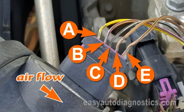
New pigtail assembly to repair the mass air flow sensor connector for the listed applications. This is a discussion on map wiring within the computer & tuning forums, part of the lsx technical help section category; These directions will likely be easy to grasp and apply. Disregard the bosch unit for now, we'll be wiring that sensor in at a later time. Shown above is the stock ls1 map connector next to a bosch style standalone three bar map sensor. He rarely does actual ls1 swaps because you can go to a junkyard and the next biggest expense in the swap is the wiring harness. Between the maf (mass air flow sensor) and engine's throttle body. All psi harnesses are made in the usa. Pink wire is from the engine sensors fuse in the underhood fuse block. The easiest is to buy the adapter wiring harness and ls1 calibrated maf from pace parts. Pin wire circuit function a 0.35 ye 492 mass air flow (maf) sensor signal b 0.8 bk/wh 451 ground c 0.5 pk 539 ignition 1 voltage d 0.35 tn 2760 low reference e 0.35 tn 472 intake air temperature sensor signal For lt1, ls1, lt4, and many other gm 3 wire maf applications. Loj is here to tell you that isn.
The individual harness part number that come in the kit is 19166568. Psi sells standalone wiring harnesses for gm gen ii, iii, iv, & v ls/lt based engines and transmissions. The first ls1 maf sensor (top left) was introduced in 1994 for use with the lt1 engine. This wire is yellow and leads to pin 31 on the ls1 c2 ecu connector. This time on spptv i do my best to pass on the knowledge i have gained through the years building over 20 stand alone ls wiring harnesses.
3 Wire To 5 Wire Maf Adapter Help Ls1tech Camaro And Firebird Forum Discussion from ls1tech.com Pin b is the switched power wire, that should come from the pink eng sen fuse or efi relay. Pin a maf output is the main pin you'll want to test for maf errors. These directions will likely be easy to grasp and apply. Pink wire is from the engine sensors fuse in the underhood fuse block. I need to wire a ls3 map pigtal onto my ls1 harness, does anyone have the diagram for the ls3. The controller kit came with the standard cartridge type maf sensor that is mounted in a cold air intake tube. Each part ought to be placed and connected with different parts in particular way. If not, the structure won't work as it ought to be.
Black/red is grounded at the front of the engine, near the right valve cover, attached to block brown/white goes to the ecm black and black both go to ecm the 04 diagram shows maf wiring as being:
Ls engine swap wiring diagram basic engine wiring diagram chevy chevy ls1 swap wiring diagram swap wiring harness ls1 coil wiring. Pin b is the switched power wire, that should come from the pink eng sen fuse or efi relay. I'm reading these maf threads and everyone keeps mentioning the g8 maf wiring. Between the maf (mass air flow sensor) and engine's throttle body. Loj is here to tell you that isn. 98 camaro engine wiring diagram ls1 var 1998 pdf for tracker starter circuit wireing harness 2004 gm ls6 efi pcm ignition 1 feed ls1tech g ecu pinout 1999 2002 my pro street 93 lt1 to conversion o2 jaguar specialties corvette fuel line firebird procharger need boss rt3 chevy and pontiac 1993 alternator 97 r. It sounds like this is an issue with the wires leading to the maf. Pink wire is from the engine sensors fuse in the underhood fuse block. This other wire can be removed as well. This time on spptv i do my best to pass on the knowledge i have gained through the years building over 20 stand alone ls wiring harnesses. Pin wire circuit function a 0.35 ye 492 mass air flow (maf) sensor signal b 0.8 bk/wh 451 ground c 0.5 pk 539 ignition 1 voltage d 0.35 tn 2760 low reference e 0.35 tn 472 intake air temperature sensor signal It's supposed to assist all of the common user in creating a correct program. This brown wire will lead you to a connector that will have another wire on it.
Any wire not highlighted does not get touched, its required for proper engine/transmission control. 1996 1998 map sensor circuit diagram 1 obd1 honda tech efi 3 wire wiring gm how to service an accord test a odyssey 2018 ford dtc p0107 your ls1 tpap color of wires maf 2 0l neon obdi my pro civic done page 2001 d16z6 code 2007 cr v engine s2000 dodge crank 2005 toyota for 2000 chevy s10 isuzu iat pressure 4l chevrolet malibu. These harnesses include the gen ii lt1/lt4, gen iii (24x) ls1/ls6 and vortec truck engines as well as gen iv (58x) ls2, ls3, ls7, & vortec and gen v lt / ecotec3 engines. Z32 wiring diagram wiring diagram 500 whether your an expert nissan 300zx mobile electronics installer nissan 300zx fanatic or a novice nissan 300zx enthusiast with a 1995 nissan 300zx a car stereo wiring diagram can save yourself a lot of time. The wire in painless performance kits runs a little larger than the standard;
Part 1 How To Test The Maf Sensor 2004 2008 3 5l Malibu from easyautodiagnostics.com He rarely does actual ls1 swaps because you can go to a junkyard and the next biggest expense in the swap is the wiring harness. Power brake booster vacuum source: To begin testing, reference the chart below for the ls1 map sensor wiring pinout and diagram. The gmpp ls2 controller kit is part number 19166573. Between the maf (mass air flow sensor) and engine's throttle body. Pin a maf output is the main pin you'll want to test for maf errors. New pigtail assembly to repair the mass air flow sensor connector for the listed applications. Pin b is the switched power wire, that should come from the pink eng sen fuse or efi relay.
If the wires are good, next thing i would do is get a known working maf and swap it in.
Each part ought to be placed and connected with different parts in particular way. Psi sells standalone wiring harnesses for gm gen ii, iii, iv, & v ls/lt based engines and transmissions. It's supposed to assist all of the common user in creating a correct program. Power brake booster vacuum source: Maf signal to ecm pink: Pin a maf output is the main pin you'll want to test for maf errors. These harnesses include the gen ii lt1/lt4, gen iii (24x) ls1/ls6 and vortec truck engines as well as gen iv (58x) ls2, ls3, ls7, & vortec and gen v lt / ecotec3 engines. For lt1, ls1, lt4, and many other gm 3 wire maf applications. Any wire not highlighted does not get touched, its required for proper engine/transmission control. Hello all, i am building a factory five gtm, using an ls2 crate engine, and a gmpp ls2 controller kit with e67 ecm. I'm reading these maf threads and everyone keeps mentioning the g8 maf wiring. It sounds like this is an issue with the wires leading to the maf. This wire is yellow and leads to pin 31 on the ls1 c2 ecu connector.