Home
› Circuit Diagrams Explained - Wiring Diagrams Explained How To Read Wiring Diagrams Upmation / To build a circuit you need a different diagram showing the layout of the parts on breadboard (for temporary circuits), stripboard or printed circuit board.
Circuit Diagrams Explained - Wiring Diagrams Explained How To Read Wiring Diagrams Upmation / To build a circuit you need a different diagram showing the layout of the parts on breadboard (for temporary circuits), stripboard or printed circuit board.
Circuit Diagrams Explained - Wiring Diagrams Explained How To Read Wiring Diagrams Upmation / To build a circuit you need a different diagram showing the layout of the parts on breadboard (for temporary circuits), stripboard or printed circuit board.. To build a circuit you need a different diagram showing the layout of the parts on breadboard (for temporary circuits), stripboard or printed circuit board. Signal generator using 555 timer ic: Symbols show the methods of actuation, the number of positions, the flow paths and the number of ports. Within the osi model of networking, logical diagrams are referred to as 'l2'. Mar 21, 2016 · pneumatic circuit symbols representing these valves provide detailed information about the valve they represent.
Within the osi model of networking, logical diagrams are referred to as 'l2'. The important components of typical home electrical wiring including code information and optional circuit considerations are explained as we look at each area of the home as it is being wired. Symbols show the methods of actuation, the number of positions, the flow paths and the number of ports. They also may be drawn by different ecad software such as eplan or autocad electrical. They may have different layouts depending on the company and the designer who is designing that.
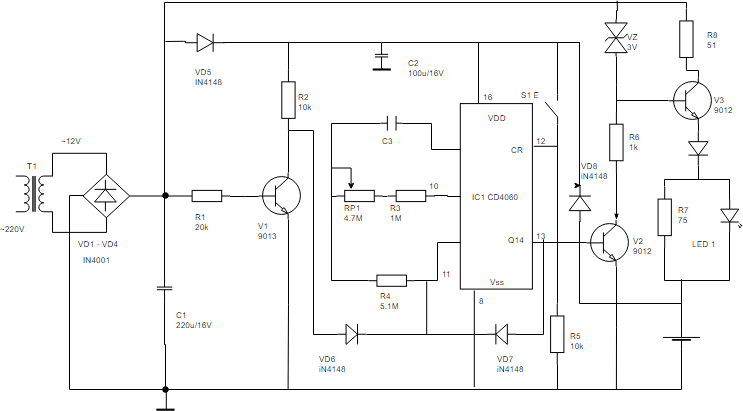
How To Create Circuit Diagram from www.visual-paradigm.com Symbols show the methods of actuation, the number of positions, the flow paths and the number of ports. Apr 17, 2020 · so i wrote an article on how to make your own circuit design from scratch. Let's explain the main parts of it and how it actually works. Signal generator using 555 timer ic: Or start reading about the voltage divider , ohm's law , thevenin's theorem or kirchhoff's laws. This circuit is necessary because, with the frequency meter in place we must have a signal whose frequency is known to us. Jul 01, 2012 · the circuits include free schematics and many of them also include explanations on how the circuit works and pcb layout. Here is a brief breakdown of how to read a symbol.
Logical network diagrams focus in on how traffic flows across the network, ip addresses, admin domains, how domains are routed, control points, and so on.
They also may be drawn by different ecad software such as eplan or autocad electrical. Mar 21, 2016 · pneumatic circuit symbols representing these valves provide detailed information about the valve they represent. Signal generator using 555 timer ic: Here is a brief breakdown of how to read a symbol. Apr 17, 2020 · so i wrote an article on how to make your own circuit design from scratch. 66/11 kv outdoor substation single line diagram. Or start reading about the voltage divider , ohm's law , thevenin's theorem or kirchhoff's laws. The actual layout of the components is usually quite different from the circuit diagram. The home electrical wiring diagrams start from this main plan of an actual home which was recently wired and is in the final stages. Dec 29, 2020 · wiring diagrams may follow different standards depending on the country they are going to be used. The important components of typical home electrical wiring including code information and optional circuit considerations are explained as we look at each area of the home as it is being wired. Jun 13, 2016 · signal generator circuit and schmitt trigger have been explained below. First of all we will talk about 555 ic based square wave generator, or should i say 555 astable multivibrator.
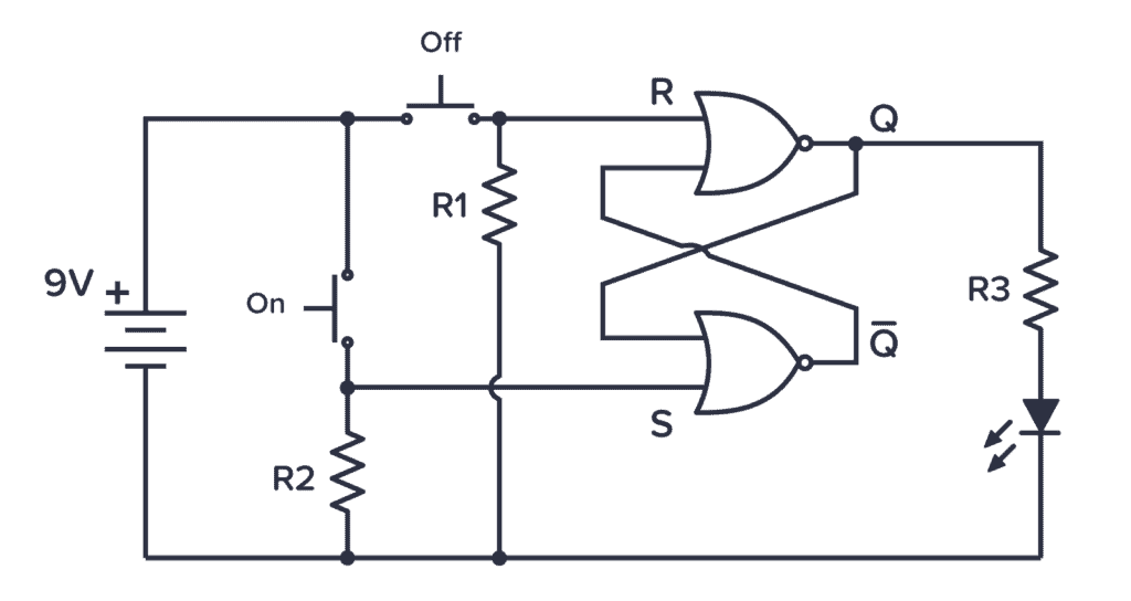
The two most common network diagrams you'll come across are physical and logical. First of all we will talk about 555 ic based square wave generator, or should i say 555 astable multivibrator. Circuit symbols are used in circuit diagrams showing how a circuit is connected together. Apr 17, 2020 · so i wrote an article on how to make your own circuit design from scratch. This circuit is necessary because, with the frequency meter in place we must have a signal whose frequency is known to us.
How To Read Circuit Diagrams For Beginners from startingelectronics.org The home electrical wiring diagrams start from this main plan of an actual home which was recently wired and is in the final stages. Or start reading about the voltage divider , ohm's law , thevenin's theorem or kirchhoff's laws. Circuit symbols are used in circuit diagrams showing how a circuit is connected together. Jun 13, 2016 · signal generator circuit and schmitt trigger have been explained below. This circuit is necessary because, with the frequency meter in place we must have a signal whose frequency is known to us. Dec 29, 2020 · wiring diagrams may follow different standards depending on the country they are going to be used. 66/11 kv outdoor substation single line diagram. But i would also recommend you checking out creating circuit schematic diagrams for an overview of the process.
The important components of typical home electrical wiring including code information and optional circuit considerations are explained as we look at each area of the home as it is being wired.
Apr 17, 2020 · so i wrote an article on how to make your own circuit design from scratch. Within the osi model of networking, logical diagrams are referred to as 'l2'. The two most common network diagrams you'll come across are physical and logical. Jun 13, 2016 · signal generator circuit and schmitt trigger have been explained below. But i would also recommend you checking out creating circuit schematic diagrams for an overview of the process. They may have different layouts depending on the company and the designer who is designing that. Logical network diagrams focus in on how traffic flows across the network, ip addresses, admin domains, how domains are routed, control points, and so on. Signal generator using 555 timer ic: To build a circuit you need a different diagram showing the layout of the parts on breadboard (for temporary circuits), stripboard or printed circuit board. First of all we will talk about 555 ic based square wave generator, or should i say 555 astable multivibrator. The important components of typical home electrical wiring including code information and optional circuit considerations are explained as we look at each area of the home as it is being wired. Let's explain the main parts of it and how it actually works. Symbols show the methods of actuation, the number of positions, the flow paths and the number of ports.
Within the osi model of networking, logical diagrams are referred to as 'l2'. The important components of typical home electrical wiring including code information and optional circuit considerations are explained as we look at each area of the home as it is being wired. They also may be drawn by different ecad software such as eplan or autocad electrical. First of all we will talk about 555 ic based square wave generator, or should i say 555 astable multivibrator. To build a circuit you need a different diagram showing the layout of the parts on breadboard (for temporary circuits), stripboard or printed circuit board.
Schematic Symbols The Essential Symbols You Should Know from www.build-electronic-circuits.com Symbols show the methods of actuation, the number of positions, the flow paths and the number of ports. The actual layout of the components is usually quite different from the circuit diagram. Signal generator using 555 timer ic: First of all we will talk about 555 ic based square wave generator, or should i say 555 astable multivibrator. This circuit is necessary because, with the frequency meter in place we must have a signal whose frequency is known to us. Mar 21, 2016 · pneumatic circuit symbols representing these valves provide detailed information about the valve they represent. They also may be drawn by different ecad software such as eplan or autocad electrical. Logical network diagrams focus in on how traffic flows across the network, ip addresses, admin domains, how domains are routed, control points, and so on.
To build a circuit you need a different diagram showing the layout of the parts on breadboard (for temporary circuits), stripboard or printed circuit board.
First of all we will talk about 555 ic based square wave generator, or should i say 555 astable multivibrator. The home electrical wiring diagrams start from this main plan of an actual home which was recently wired and is in the final stages. Signal generator using 555 timer ic: Apr 17, 2020 · so i wrote an article on how to make your own circuit design from scratch. Dec 29, 2020 · wiring diagrams may follow different standards depending on the country they are going to be used. They also may be drawn by different ecad software such as eplan or autocad electrical. Within the osi model of networking, logical diagrams are referred to as 'l2'. This circuit is necessary because, with the frequency meter in place we must have a signal whose frequency is known to us. The actual layout of the components is usually quite different from the circuit diagram. They may have different layouts depending on the company and the designer who is designing that. Web pages with original circuits and descriptions these pages contains original content from the authors on each page. Symbols show the methods of actuation, the number of positions, the flow paths and the number of ports. But i would also recommend you checking out creating circuit schematic diagrams for an overview of the process.