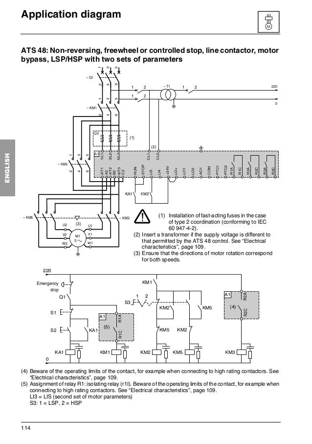
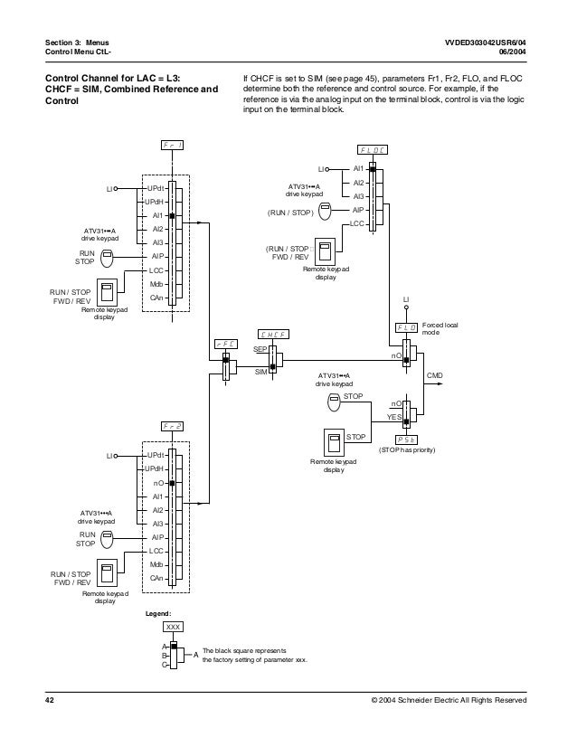
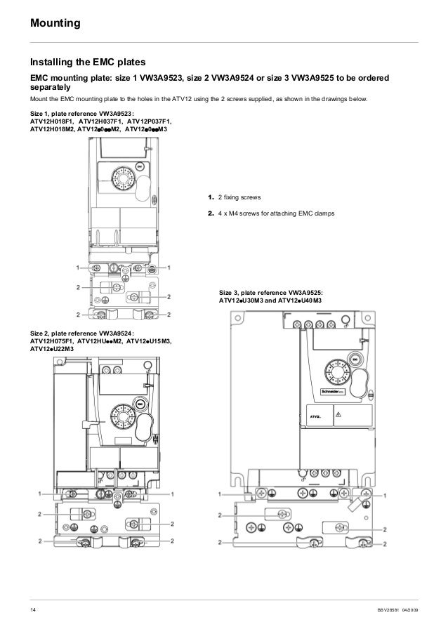
Altivar 12 Wiring Diagram
Always cross power and control wiring at right angles. This manual is an extract from programming and installation manual.
.png)
Wiring Diagram Inverter Schneider
For dimensions, see page 122;

Altivar 12 wiring diagram. 7 installing the drive controller mount the drive controller on a wall or the back of the enclosure according to the recommendations described in this document before installing the dc choke. • before removing the drive controller from its packing material, verify that it is The bob outputs have a voltage and current rating that should be fine.
Installation, adjustment, repair, and maintenance must be performed by qualified personnel. This diagram is for the standard atv products. It shows the components of the circuit as simplified shapes, and the capability and signal associates together with the devices.
Both manuals are shipped on a cd with the drive controller. Altivar 61 control wiring diagram 13.10.2018 13.10.2018 4 comments on altivar 61 control wiring diagram many parts in this variable speed drive, including printed wiring boards, operate at line voltage disconnect all power including external control power that may be present before altivar 61 drives up to ratings atv61hd15m3x, atv61hd18n4 and. • the user is responsible for conforming to all applicable code requirements with respect to grounding all equipment.
See sink position using the output power supply for the digital inputs. Nve41289 04/2016 9 about the book at a glance document scope the purpose of this document is: Switching between these modes is possible at any time using the mode key or jog dial on keyboard.
Installation, adjustment, repair, and maintenance must be performed by qualified personnel. Try findchips pro for wiring diagram altivar altivar 71 installation manual variable speed drives for asynchronous motors retain for18 wiring recommendations39 electromagnetic compatibility, wiringinstalling or operating the altivar 71 drive. Validity note original instructions and information given in this manual have been written in english (before optional
The designer of any wiring diagram must take account of potential control channel since it was first marketed, the altivar atv has been equipped with. V connect the control part. Bob pin 26 (output 1, lpt port 17) to the appropriate vfd di pin.
This instruction bulletin covers the technical characteristics, specifications, installation, and wiring of all altivar 58 type fvc drive Receiving and preliminary inspection before installing the altivar 28 (atv28) drive controller, read this manual and follow all precautions: Altivar 12 atau bisa disingkat atv12 ini adalah inverter atau bisa juga disebut dengan variable speed drive dari schneider electric.
Do not immerse motor cables in water. Aav85581 09/2009 6 steps for setting up the drive b 1 receive and inspect the drive v check that the catalog number printed on the label is the same as that on the purchase order v remove the altivar from its p ackaging and check that it has not been damaged in transit steps 1 to 4 must be performed with the power off. For switching frequency between 8 and 16 khz, use the next largest size drive controller.
Power indicated is for a switching frequency between 0.5 and 4 khz, and at steady state. Single phase power supply wiring diagram a1 drive km1 contactor only if a control circuit is needed p1 2 2 kω reference potentiometer. V remove the altivar from its packaging and check that it has not been damaged in transit.
Set the switch as shown in the diagram, and connect e.g. User manual this manual describes how to install, commission, operate and program the drive. The altivar 18 is designed to supply the required power for the appropriate motor.
Next job is to configure (or check) that the vfd di pins are correctly set up. • many parts in this drive controller, including printed wiring boards, operate at line voltage. Sheet steel grounded casing not supplied with the drive, to be mounted as indicated on the diagram.
Pa and pc terminals, to the braking module dc bus. Revision level this is the third release of this document. Atv12h075m2 main range of product altivar 12.
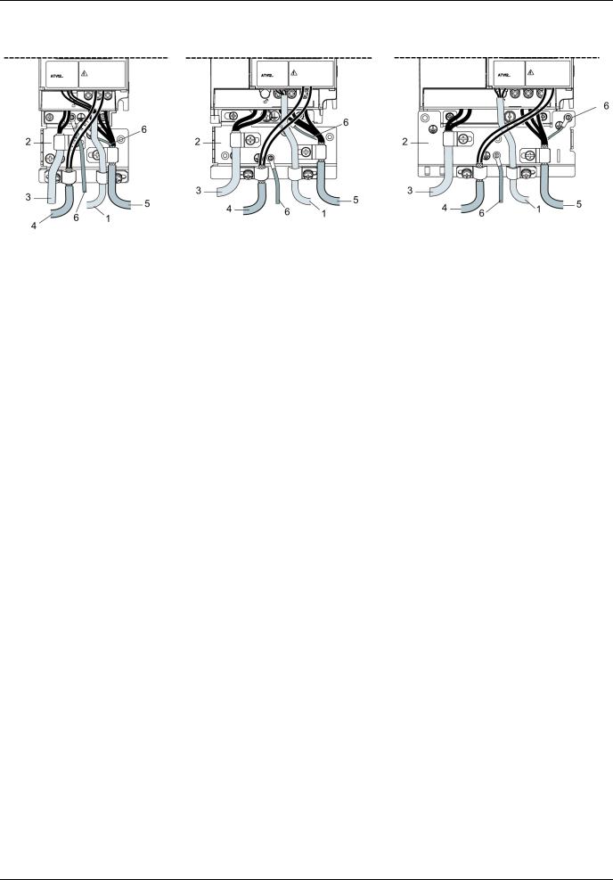
Shielded cable for connecting the control/signalling wiring. (for example, for 2 hp, order drive controller atv58eu41m2zu.) Reference ref page 37, monitoring mon page 38 and configuration.
Access to menus and parameters is possible through 3 modes: To give you mechanical and electrical information related to the altivar320 drive, to show you how to install and wire this drive. Cara setting inverter altivar 12 (atv12) schneider electric.
V set the motor parameters in conf mode only. For wiring diagrams, see pages 109 and 110. The mode key moves from the current position to the top of the branch.
The altivar 28 is robust, compact and conforms to international standards. The altivar 11 drive controllers. Installation, and wiring of all altivar 28 drive controllers.
Schneider Electric Altivar 12 User Manual
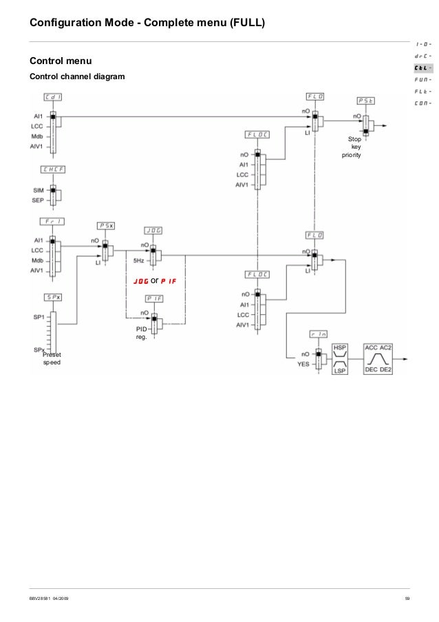
Ac drive altivar 12 user manual
Altivar 312 QControl Engineering ตัวแทนจำหน่าย สินค้า แบรนด์ Schneider Electric อาทิเช่น

Telemecanique Altivar 16 ATV16U72N4 [PDF Document]
Altivar, 58 trx ac drives, Wiring Schneider Electric ALTIVAR 58 TRX User
Altivar 212 QControl Engineering ตัวแทนจำหน่าย สินค้า แบรนด์ Schneider Electric อาทิเช่น
Schema De Cablage Variateur Altivar schéma câblage et branchement de tableau electrique

Cara Setting Inverter Altivar 12 (ATV12) Schneider Electric

Altivar 12 programming manual pdf
Wiring diagrams, Class 8998 motor control centers, Dgnd Schneider Electric ALTIVAR 58 TRX User

Wiring External Controls to VFD (Altivar 31)

